NSW Rail Motors Class Index
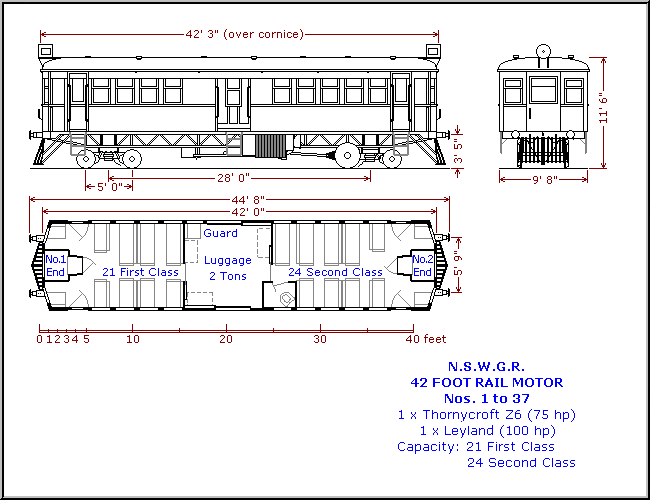
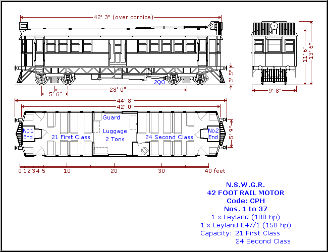
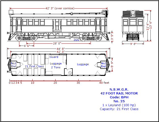
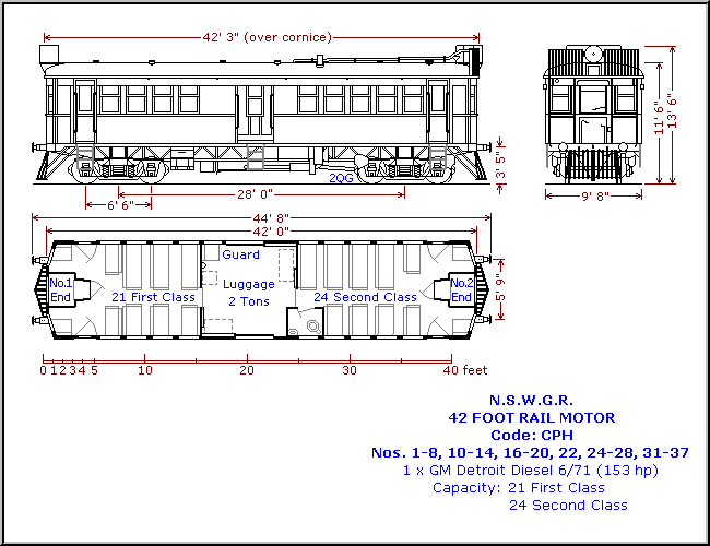
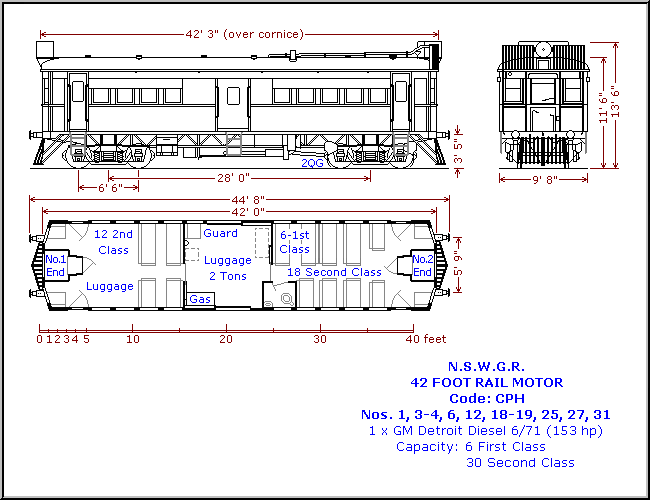
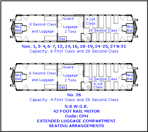
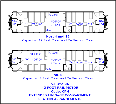
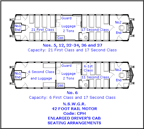
This index provides a complete reference to every class of rail motor that has operated on the New South Wales railway network. From the humble 42-Foot CPH Class of the 1920s through to the modern Xplorer and Endeavour fleets, each entry links to detailed technical and historical information. Use this index as your starting point for researching any specific vehicle class in the NSW rail motor fleet.
Quicklinks
The Rail Motor Society
NSW Rail Motors
© 2026 The Rail Motor Society. All Rights Reserved.


